
Introduction: Why Design Deliverables Matter in AV Projects
“AVIXA’s 2023 IOTA projects the global professional AV industry to reach $402 billion by 2028.” – Source
When budgets are tight and expectations are high, the difference between a smooth AV integration and a costly misfire often comes down to one thing: design deliverables. In audio visual system design, drawings, schematics, and documentation are the blueprint that keeps teams aligned, protects budgets, and ensures your investment performs as promised.
What “AV system design deliverables” actually include (beyond a parts list)
A proper AV design package is far more than a bill of materials. Expect a coordinated set of documents that align scope, performance, and installation details, such as:
- System line drawings and signal flow diagrams for audio, video, control, and network
- Floor plans, reflected ceiling plans, and interior elevations showing device locations and sightlines
- Rack elevations, equipment layouts, and thermal/power load considerations
- Cable schedules with types, pathways, terminations, labeling conventions, and lengths
- Network topology (VLANs, QoS, multicast/IGMP plans) and addressing schemes for AV over IP
- DSP project files (presets, EQ, routing, automixing) and control system GUI mockups
- Mounting details, engineering notes, and structural coordination requirements
- Compliance items (ADA assistive listening, fire-stopping notes, code references)
- Submittals and cut sheets tied to the design revision set
- Test plans, commissioning checklists, and acceptance criteria
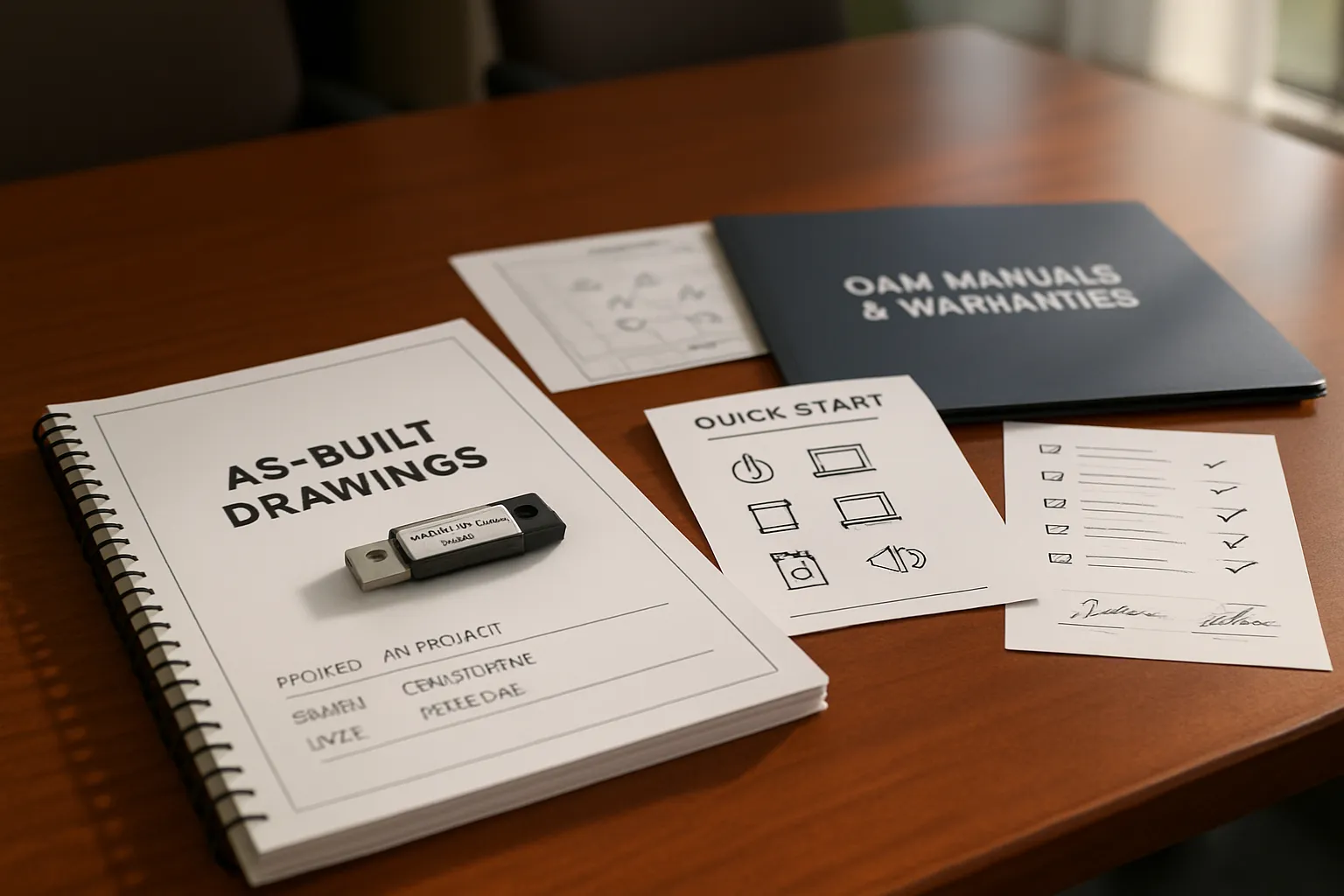
- As-built drawings and O&M handover documentation (training guides, warranty info)
These deliverables create a shared source of truth so every stakeholder – from facilities to IT to the installer – knows exactly what “done right” looks like.
How drawings and schematics reduce risk, rework, and budget creep
High-quality drawings and schematics are risk management tools for your audio visual business:
- Scope clarity: Eliminates ambiguity, enabling apples-to-apples bids and preventing scope gaps
- Fewer change orders: Clear pathways, device counts, and cable types reduce mid-project surprises
- Faster installation: Installers work from precise layouts and labeling standards, cutting labor time
- Better coordination: Early structural, electrical, and IT alignment prevents conflicts in the field
- Predictable performance: DSP and control files tie the design to measurable outcomes
- Easier support: As-builts and labeling speed troubleshooting and future upgrades
- Lifecycle value: Documented standards make expansions and migrations simpler and less risky
In short, design documentation is your best defense against rework and budget creep – and your best bet for on-time, on-budget AV system design.
Who this guide is for: corporate, retail, churches, restaurants, sports bars
This buyer’s guide is written for non-technical decision makers and savvy operators who need practical, vendor-agnostic clarity:
- Corporate IT, facilities, and workplace experience teams
- Retail brand, VM/marketing, and store development teams
- Churches and faith-based organizations planning worship AV
- Restaurants and hospitality venues
- Sports bars and entertainment operators
If you’re planning to design AV, refresh spaces, or standardize your fleet, this guide will help you ask the right questions and evaluate proposals with confidence.
What you’ll learn in this buyer’s guide to audio visual system design
By the end, you’ll know:
- What a complete AV design package includes – and what’s often missing from weak bids
- Which drawings, schematics, and files you should insist on for risk control
- How labels, naming conventions, and cable schedules prevent chaos during installation
- What to expect from DSP projects and control UI design before a single device ships
- How to evaluate rack layouts, power/thermal planning, and AV-over-IP network design
- What commissioning, as-builts, and handover documentation should look like
- How to compare AV proposals beyond price, and protect your budget from change orders
Whether you manage one room or a multi-site rollout, this guide gives you a clear framework to secure better outcomes from your audio visual design – and a playbook to hold partners accountable.
From Schematic to Handover: What’s in an AV Design Package (Phase-by-Phase)
A professional AV system design package is built in phases. Each phase adds clarity, mitigates risk, and ensures the audio visual system design aligns with your goals, budget, and schedule. Here’s exactly what to expect at each step – and how to use the deliverables to keep your project on track.
Phase 1 – Discovery & Scope
- Needs analysis summary: stakeholders, goals, success criteria, constraints
- Room data sheets: dimensions, seating, finishes, ambient light, infrastructure
- Use cases: presentations, hybrid meetings, overflow, signage, broadcast
- Functional narrative: what the system must do (not how), per space type
Why it matters: This is where you define outcomes and avoid scope drift later. It sets the foundation for a realistic AV system design, budget, and timeline.
Phase 2 – Schematic Design (SD)
- High-level block diagrams showing sources, processing, transport, and destinations
- Preliminary display sizing and viewing geometry (DISCAS-compliant)
- Budgetary BOM and options with cost ranges and trade-offs
“AVIXA V201.01 (DISCAS) recommends minimum image height = 1/5 of farthest viewer distance for Basic Decision Making and 1/3 for Analytical Decision Making.” – Source
Why it matters: This phase aligns expectations – what the system will be, how big screens should be, and what it will likely cost – before anyone drills a hole.
Phase 3 – Design Development (DD)
- Floor plans showing device locations, screen sizes, sightlines, and coverage
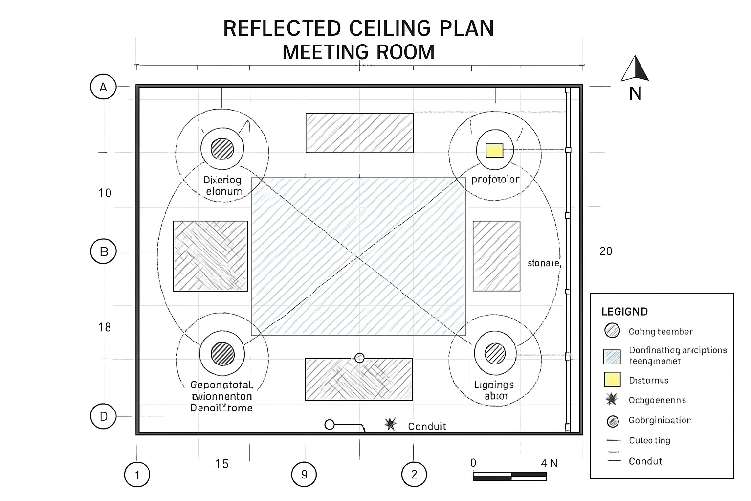
- Reflected ceiling plans (RCP) for speakers, mics, sensors, and conduit stubs
- Wall elevations and mounting details for displays, touch panels, and I/O plates
- Riser diagrams for AV backbones and inter-room infrastructure
Why it matters: DD eliminates field guesswork by coordinating with architects, GC, and IT so power, pathways, and structure are ready for the AV scope.
Phase 4 – Construction Documents (CD)
- Single-line/signal-flow schematics for audio, video, control, and network
- Device schedules with model numbers, quantities, power/BTU, and accessories
- Cable schedules (types, terminations, IDs, lengths, pathways)
- Rack elevations and thermal/power layout; I/O lists and port maps
- Labeling schema and naming conventions for rooms, racks, devices, and cables
Why it matters: CDs are the instruction manual for build and installation. Clear documentation reduces change orders, accelerates install, and safeguards quality.
Phase 5 – Programming & Files
- DSP project files (routing, EQ, automix, presets) and documentation
- Control code, logic flow, and UI mockups for touch panels/web/mobile
- Network/IP plan: VLANs, QoS, IGMP, addressing, access policy, time sync
- Final naming conventions: devices, streams, rooms, presets, logs
Why it matters: This is how your audio visual design becomes usable and supportable. Early UI and preset reviews prevent rework and ensure user acceptance.
Phase 6 – Commissioning & Handover
- Test plans and performance verification (SPL/STI, latency, switching, camera shots)
- As-built drawings and final rack elevations reflecting field changes
- O&M manuals: user guides, backup procedures, firmware baselines
- Training records, administrator handoff, warranties, and support SLAs
Why it matters: Commissioning proves the system meets the design av intent; handover equips your team to operate, support, and scale with confidence.
Deliverables by Phase
| Phase | Typical Documents | Who Uses Them (client/IT/GC/integrator) | Decisions Finalized at This Stage |
|---|---|---|---|
| Phase 1 – Discovery & Scope | Needs analysis, room data sheets, use cases, functional narrative | Client, IT, Integrator | Goals, success criteria, room list, budget range, constraints |
| Phase 2 – Schematic Design (SD) | High-level block diagrams, preliminary DISCAS display sizing, budgetary BOM | Client, IT, Finance, Integrator | Solution approach, display size ranges, budgetary options, go/no-go to DD |
| Phase 3 – Design Development (DD) | Floor plans, RCPs, wall elevations, mounting details, riser diagrams | Architect/GC, Trades, IT, Integrator | Device locations, power/data rough-ins, pathways, structural coordination |
| Phase 4 – Construction Documents (CD) | Single-line schematics, device and cable schedules, rack elevations, I/O lists, labeling schema | Integrator, GC, IT | Final counts and models, terminations, labels, rack build plan, procurement |
| Phase 5 – Programming & Files | DSP files/presets, control code and UI mockups, network/IP plan, naming conventions | Integrator Programmers, IT/Security, Client Superusers | UI/UX, presets, IP ranges, VLAN/QoS policy, monitoring and access |
| Phase 6 – Commissioning & Handover | Test plans, performance verification results, as-builts, O&M manuals, training records, warranties | Client Ops/IT, Facilities, Integrator Service | Acceptance sign-off, training completion, warranty start, service plan |
Use this phase-by-phase map to evaluate proposals from any audio visual business. If a deliverable is missing, ask why. Thorough documentation is the best insurance policy for on-time, on-budget AV system design that works on day one – and keeps working for years.
Infrastructure Drawings: Plans, RCPs, Elevations, and Mounting Details
Infrastructure drawings translate intent into precise, buildable instructions. They coordinate architects, trades, and integrators so devices end up in the right place, at the right height, with the right support and power – on the first try.
Floor plans: device locations, conduit/home-run paths, outlet heights
- Device locations: screens, cameras, touch panels, plate locations, racks/IDF ties
- Pathways: conduits, cable tray, core drills, and home-runs to racks or network rooms
- Power and data: receptacle counts, outlet heights (AFF), dedicated circuits, UPS feeds
- Dimensions and offsets: sightline axes, ADA clearances, door swings, furniture references
- Coordination notes: slab penetrations, firestopping, rated-wall penetrations, pull strings
Why it matters: Floor plans lock in the “where” for AV – preventing costly relocations and rework when walls close.
RCPs: speaker/microphone grids, projector paths, sensor layouts, lighting zones
- Speaker grids with coverage rings; sub placement and downfill/aiming notes
- Beamforming mic lobes and ceiling mic pickup areas; avoid HVAC and luminaires
- Projector locations with throw/offset, mounts, and screen centerline alignment
- Sensor layouts (occupancy/daylight) and coordination with control zoning
- Lighting zones and dimming interfaces to support camera exposure and visibility
Why it matters: The RCP resolves clashes above the ceiling – plenum space, structure, ducting – before field install begins.
Wall elevations and sections: mounting heights, ADA clearances, cable pass‑throughs
- Mounting heights (AFF) for displays, speakers, cameras, touch panels, and plates
- ADA and code: reach ranges, protrusion limits, knee/toe clearances at lecterns
- Back-of-display sections: mount type, tilt/aim, cable bend radius, pass-through location
- Reinforcement: blocking details for heavy loads; fastener specs for substrate types
- Finish coordination: bezel clearances, recessed niches, trim bezels, conduit stubs
Why it matters: Elevations make field layout unambiguous and keep you compliant with accessibility and safety requirements.
Detail sheets: back boxes, blocking, seismic/rigging notes, sightline callouts
- Back boxes and mud rings: sizes, depths, gang counts, trim kits, flange/bezel specs
- Blocking details: wood/steel plate locations with centerlines and fastener patterns
- Seismic/rigging: load paths, safety cables, anchors, and local jurisdiction notes
- Sightlines: eye height assumptions, top/bottom-of-image callouts, VTC camera shots
- Special conditions: glass walls, movable partitions, acoustical clouds, lift clearances
Why it matters: Details eliminate field interpretation – especially for heavy, overhead, or motorized equipment.
Issue sets and versioning: 30/50/90/IFC and addendum/change-order workflow
- Progressive sets: 30% (concept), 50% (basis of design), 90% (near-final), IFC (Issued for Construction)
- Title blocks and revision clouds: each change logged with delta tags and dates
- Coordination cadence: distribute to GC/MEP/IT; track RFIs and collision resolutions
- Addendum and ASI process: formal updates post-IFC; tie to change orders as needed
- As-built capture: redlines during install roll into final record drawings and O&M
Why it matters: Version control keeps trades aligned, controls scope, and provides a defensible record for schedule, cost, and quality management.
Schematics and Signal Flow: Reading the Heart of an AV System
Schematics are the truth serum of an AV project. They reveal exactly how signals move, what connects to what, and where failures can occur – so you can plan, build, and support with confidence.
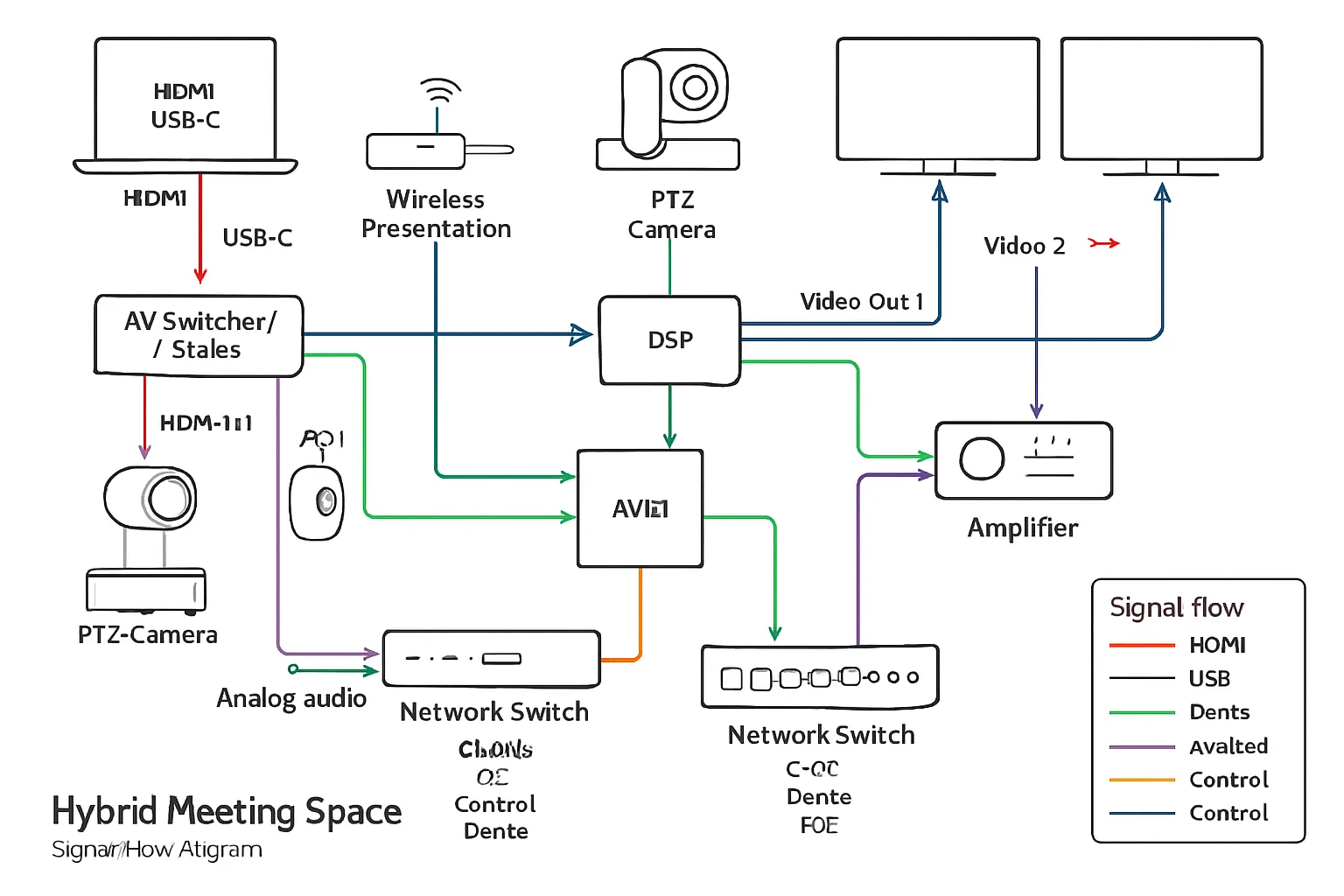
Single-line diagrams: sources, switchers, DSP, amps, endpoints, transports (HDMI/HDBaseT/Dante/USB)
- Identify every source: room PC, laptops (HDMI/USB‑C), wireless presentation, PTZ camera(s)
- Route through the core: matrix/switcher/scaler, DSP for audio processing and AEC
- Define transports: HDMI/HDBaseT for video, Dante for audio-over-IP, USB for conferencing
- Endpoints: displays, projectors, USB capture, loudspeakers, assistive listening, recorders
- Show clocking/sync where applicable (Dante PTP, word clock) and EDID/HDCP notes
Why it matters: Single-line drawings let stakeholders validate functionality before procurement and give installers an unambiguous roadmap.
Control and network topology: VLANs/QoS, control processors, switches, PoE budgets
- Segmentation: dedicated VLANs for AV-over-IP (Dante/AVB), control, and corporate data
- QoS/class-of-service for low-latency audio and camera streams; IGMP snooping for multicast
- Control processor relationships: touch panels, button stations, occupancy sensors, relays/IO
- PoE/PoE+ budgets: tabulate draw vs. switch capacity, with redundancy for critical devices
- Security and access: management interfaces, ACLs, NTP, firmware baselines, monitoring
Why it matters: A clear network/control schematic prevents broadcast storms, power shortfalls, and security gaps on day one.
Riser diagrams: floor-to-floor raceways, fiber/copper backbone, labeling
- Vertical pathways: ladder racks, sleeves, and conduits between IDF/MDF and rooms
- Media choices: fiber trunks for 10/40Gb aggregation; shielded copper for PoE endpoints
- Demarcations and patching: panel IDs, strand counts, adapter types, slack management
- Labeling: room-rack-panel-port conventions tied to the cable schedule and as-builts
- Redundancy: A/B diverse paths for core links and critical spaces (boardroom, NOC)
Why it matters: Riser diagrams coordinate trades and ensure backbone capacity and resiliency scale with your audio visual business.
Best practices: line weights, connector labels, signal directions, reference tags, sheet indexing
- Line weights and styles: differentiate AV-over-IP vs. baseband vs. control vs. power
- Connector labels: port names and types (HDMI In 1, Dante Rx 1–8, USB 3.0 Host)
- Signal direction arrows and flow left-to-right for readability; avoid crossovers
- Reference tags: call out related sheets (RCPs, elevations, rack elevations) and device IDs
- Sheet indexing and revision control: consistent title blocks, delta clouds, version dates
Pro tip: If you can “trace a call” from laptop to far-end participant on paper, you’ll save hours in the field. Clear schematics turn complex av system design into predictable, supportable systems.
Schedules, BOMs, Cable Lists, and Labeling Standards
The “paperwork” behind an AV system design is what turns a concept into a buildable, supportable solution. Accurate schedules, BOMs, cable lists, and consistent labeling reduce risk, speed installation, and make ongoing support predictable.
Device schedules and BOMs: manufacturer, model, firmware, accessories, quantities
A solid device schedule and bill of materials (BOM) should read like a procurement and build playbook. Include:
- Identification: manufacturer, model, part number, device tag (ties to drawings)
- Function: role in system (e.g., “Room switcher/scaler,” “DSP core,” “PTZ camera”)
- Firmware/driver: minimum tested firmware, plugin/driver versions, licensing keys
- Accessories: mounts, brackets, bezels, power supplies, SFPs, input cards, cables
- Quantities and location: count per room and total; rack/space association
- Power/thermal: voltage, current/PoE class, BTU/hr, UPS circuiting
- Network: port counts/types, VLAN role, multicast notes, management access
- Compliance: plenum/listings, ADA requirements, local code notes
- Notes: alternates, color/finish, region codes, EOL status, long-lead risks
- Traceability: asset/serial capture plan, warranty term, support SKU
Best practices:
- Tie every schedule line to a device tag on single-line schematics and rack elevations.
- Specify tested firmware baselines to avoid regressions during commissioning.
- Include approved alternates and substitution rules to protect schedule and cost.
Cable schedule: exact types, lengths, terminations, plenum ratings, pathways
The cable schedule eliminates guesswork in the field and ensures performance margins:
- Type/spec: Cat6A F/UTP CMP, OM4 MM fiber, OS2 SM fiber, 16/2 plenum speaker, RG‑6 quad shield, active optical HDMI/DP
- Signal/protocol: HDMI 2.1 FRL, HDBaseT, USB 3.x, Dante, analog line‑level, SDI, control (RS‑232/IR/GPIO)
- Length: measured length plus service loops (typically 10–15% slack, min. 3–6 ft at rack and device)
- Terminations: RJ45 T568B, LC/UPC, SC, XLR3M/F, Euroblock/phoenix, BNC, HDMI Type A
- Ratings: CMP/CMR, LSZH where required, shield/bonding requirements, bend radius limits
- Pathway: conduit/tray IDs, fill calculations, pull box locations, core drills, firestopping
- Label IDs: unique cable ID aligned to the labeling schema (both ends + mid‑span flag on long runs)
- Test criteria: cert thresholds (e.g., Cat6A ANSI/TIA performance), fiber loss budget, HDMI validation
Tip: Pre-calculate HDBaseT/USB extents and fiber loss to ensure chosen transports meet distance and bandwidth.
Labeling schema: device tags, room codes, cable IDs, panel/port naming
Consistent labels create end-to-end traceability from drawings to the physical build to the UI:
- Room codes: SITE-BLDG-FLR-ROOM (e.g., HQ-A-03-215)
- Device tags: ROOM-RACK-DEVTYPE-INDEX (e.g., 03-215-RK1-DSP1, 03-215-DISP1)
- Cable IDs: FROMTAG:PORT→TOTAG:PORT (short form code allowed for labels)
- Panels/ports: RK1-P01‑24, SW1‑Gi1/0/24, DSP1‑In‑01, DISP1‑HDMI‑In‑1
- Patch references: PATCH‑RK1‑P01‑24↔SW1‑Gi1/0/24 color-coded by media type
These IDs should appear on:
- Physical labels: devices, racks, plates, cables (heat-shrink/flag), panels
- Drawings: schematics, RCPs, elevations, risers, cable schedules
- Software/UI: control touch panels, room controllers, monitoring systems
Procurement readiness: alternates, long-lead items, and obsolescence planning
Protect your timeline and budget by planning ahead:
- Long-lead tracking: identify >6–8 week items (LED, specialty optics, DSP cores, control processors, SFPs)
- Approved alternates: list at BOM line level with “no change to function” notes and pre-approved pricing deltas
- EOL monitoring: flag end-of-life parts; specify last-buy dates and successor models
- Spares strategy: N+1 for critical devices (switcher cards, PSUs, SFPs, DSP engines)
- Firmware lock: define tested firmware at time of submittals; control upgrade window post‑commissioning
- Logistics: staggered deliveries by phase (rough‑in, rack build, trim‑out), serial capture, DOA contingency
- Warranty and SLAs: capture terms, RMA process, and response expectations for mission‑critical spaces
A procurement-ready AV system design doesn’t just list parts – it anticipates supply chain variability and keeps your project moving.
Labeling and naming conventions
| Object (Device/Cable/Port/Patch/Room) | Example ID format | Purpose | Where It Appears (tag, label, drawing, UI) |
|---|---|---|---|
| Device | 03-215-RK1-DSP1 | Unique device identification tied to room and rack | Device tag, rack label, schematics, rack elevation, UI device list |
| Device | 03-215-DISP1 | Distinguish endpoints of same type per room | Elevations, floor plan, UI source/destination selection |
| Cable | 03-215-RK1-SW1:HDMI-OUT1→DISP1:HDMI-IN1 | End-to-end traceability for testing and troubleshooting | Cable flags/heat-shrink, cable schedule, single-line, as-builts |
| Cable (short form) | CB-03-215-0017 | Field-friendly shorthand linked to full schedule | Cable label, pull sheet, test report |
| Port (rack panel) | RK1-P01-24 | Identify patch panel and position | Panel engraving, rack elevation, riser, test log |
| Port (network) | SW1-Gi1/0/24 | Map switch interface to device | Network diagram, switch config, cutover plan |
| Patch reference | PATCH-RK1-P01-24↔SW1-Gi1/0/24 | Document patching for day-1 and MACs | Patch field label, rack elevation, change log |
| Room | HQ-A-03-215 | Site/building/floor/room code for global uniqueness | Title blocks, schedules, UI room selector, asset system |
A disciplined approach to schedules, BOMs, cable lists, and labeling is what turns audio visual system design into predictable delivery. It’s also what your operations team will thank you for – every day after go‑live.
DSP, Control, and UI: The Software Deliverables You Should Receive
Software is where your av system design comes to life. Beyond hardware lists and drawings, insist on the actual project files, readable documentation, and a sensible version-control strategy so your team can operate, support, and extend the system without vendor lock-in.
DSP project files: input/output map, presets/scenes, AEC/noise reduction, gain structure
A professional audio visual system design should hand over both editable and human-readable DSP assets:
- Native project file(s): the original editable file for the DSP platform used (e.g., with all modules/blocks intact). This is your system’s “source code” for audio.
- Input/output map: clear mapping of every physical and network input to processing blocks and outputs (including Dante/AoIP channel lists, clocking, and sample rate).
- Presets/scenes: named presets for common modes (all‑hands, presentation, VC, overflow, worship, game day). Include what each preset changes and safe states for recovery.
- AEC/noise reduction: documentation of AEC reference routing, NR/AGC thresholds, gating/automixing logic, and echo path diagrams. Note microphone processing per zone.
- Gain structure: target levels at each stage, limiter thresholds, headroom policy, and meter screenshots or tables for reference.
- Commissioning notes: measurement data (SPL/STI), EQ rationale (filters by mic/speaker zone), delay alignment, and room-specific considerations.
- Exports: PDF/PNG of the DSP layout, I/O tables, preset list, and a CSV of channel names for cross-reference in drawings and labeling.
- Dependencies: firmware version, licensed features/plugins, and any third-party control modules used.
Pro tip: Ensure DSP channel names match the device tags and cable IDs in your schedules; this speeds both commissioning and future troubleshooting.
Control code & documentation: source code vs. compiled, licensing, escrow and ownership
Control systems are software projects – treat them that way so you can support and enhance your audio visual design over time.
- Source vs. compiled: receive the editable source code and the compiled/runtime package. If the vendor limits source distribution, use an escrow agreement naming you as beneficiary.
- Licensing and keys: list of required IDEs, compiler toolchains, and any licensed modules or drivers. Include license IDs, expiration, and transferability terms.
- Ownership: contract language should grant you a perpetual, non‑exclusive license to use, modify, and maintain the program for your facilities – even if you change integrators.
- Documentation:
- System architecture: processors, touch panels, gateways, and their IPs/ports.
- API/driver references: commands for displays, switchers, DSP, lighting, and shades.
- Event flow/state diagrams: how presets, sensors, and schedules interact.
- Error handling: watchdogs, retries, offline states, and alert paths.
- Security: admin credentials, encryption keys, certs, and instructions to rotate them; role-based user accounts and logging configuration.
- Commissioning checklist: feature acceptance list mapped to use cases (e.g., “VC call preset routes far-end to ceiling speakers and mutes program audio”).
If the program is tied to specific hardware serials, include that binding detail and an alternate build plan for replacements.
UI mockups: touch panel/page flows, accessibility, operator roles, preset design
Your operators should see and approve the user experience before code is frozen.
- Page flows and states: navigation map, home screen, source selection, volume/mute, camera control, lighting, shades, help/assist.
- Operator roles: basic mode (front-of-room controls), advanced mode (tech page), and admin (service) pages; clearly gated with PINs or role-based login.
- Accessibility: large targets, high-contrast color palette, consistent icons/labels, screen reader considerations for web UIs, and minimal steps for critical actions.
- Preset design: named presets tied to outcomes (Town Hall, Panel, Sermon, Game Day, Trivia Night) with visible feedback and confirmation prompts for disruptive actions.
- Multi-device layouts: size-appropriate mockups for 7–10″ touch panels, wall keypads, and web/mobile clients; orientation and scaling rules.
- Localization: plan for multi-language labels if needed; provide a translation key/value file.
Deliverables should include image/PDF mockups, a clickable prototype (if web-based), and a control style guide so future rooms maintain a consistent experience across your audio visual business.
Version control: file naming, change logs, backup/restore strategy
Durable software deliverables rely on disciplined change management.
- File naming: Site‑Bldg‑Room_System_Component_vMAJOR.MINOR.PATCH_Date (e.g., HQ‑A‑215_AV_DSP_v1.3.2_2025‑01‑15.qsys).
- Change logs: a human-readable CHANGELOG that notes what changed, why, who approved it, and rollback instructions. Tie entries to punch-list items or tickets.
- Repository: maintain a customer-owned source repo (Git or equivalent) with separate folders for DSP, control, UI assets, release builds, and documentation. Grant read access to service partners as needed.
- Backup/restore: automated on-box backups where available, off-box scheduled exports to your server, and restore testing documented with screenshots and timings.
- Configuration capture: export switch configs, IP address plans, certificates, and NTP settings alongside code releases; include a disaster recovery runbook.
- Release policy: freeze windows for major events, semantic versioning for risk signaling, and UAT sign-off criteria before production pushes.
When you receive these software deliverables – DSP projects, control code, and UI artifacts – your audio visual system design becomes maintainable, scalable, and ready for real-world operations.
Rack Elevations, Thermal, Power, and Installation Details
Racks are the backbone of reliable AV. Clear elevations, thermal and power budgets, and disciplined build standards turn a parts list into a serviceable, safe system.
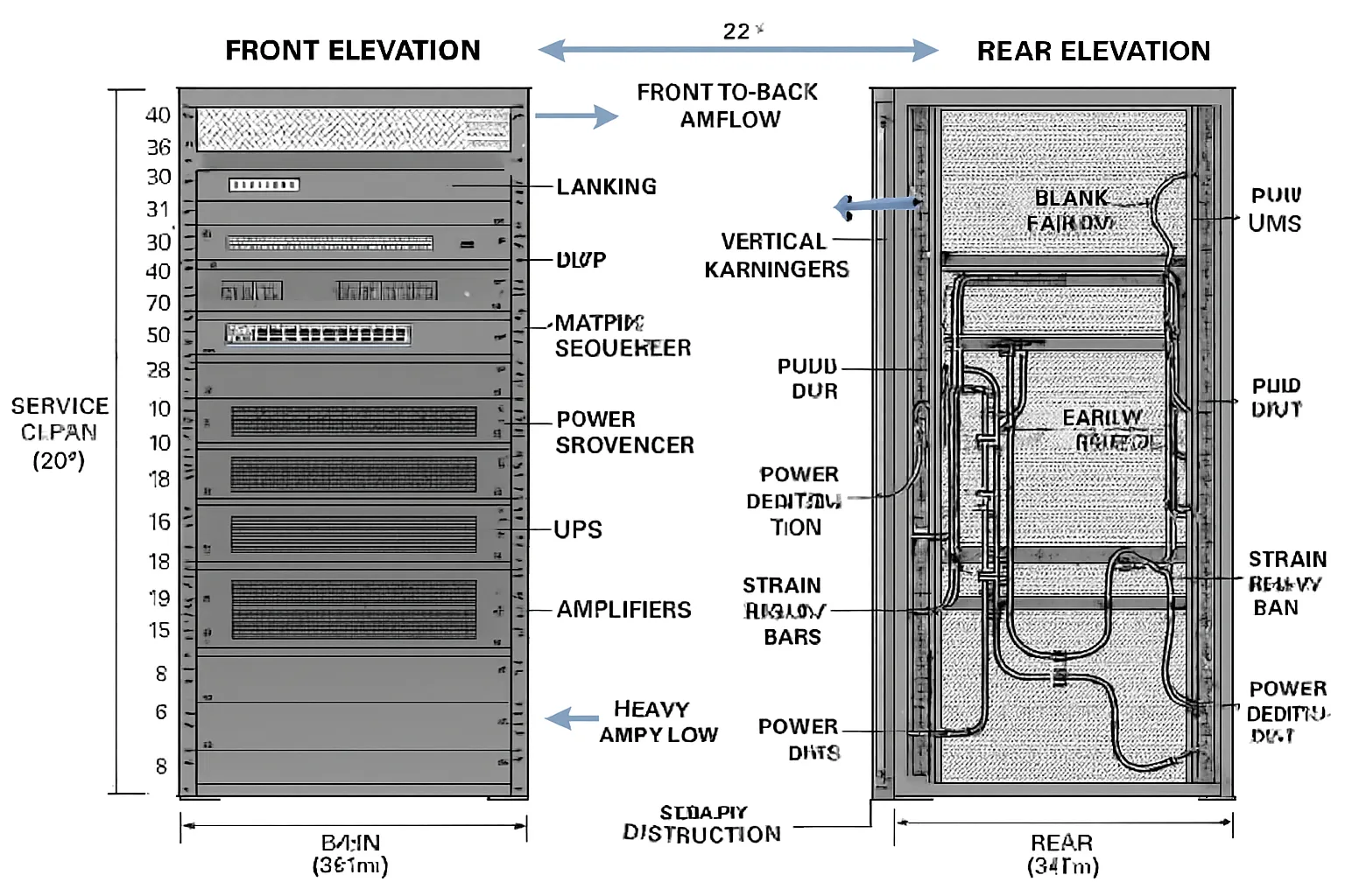
Rack elevations: RU assignments, service clearances, rear cable managers, weight distribution
- RU map: assign each device to a rack unit position with fillers/blanking panels to control airflow.
- Service clearances: maintain minimum front (36″) and rear (24″+) access; note slide rails for heavy gear.
- Rear management: vertical managers, lacing bars, and rear-mount shelves to protect connectors.
- Weight distribution: place UPS and amplifiers low, lighter gear up top; verify floor loading and anchoring.
- Accessibility: label each RU and device tag; include patch panels for modularity and faster swaps.
Thermal plan and power: BTU estimates, airflow direction, UPS/surge, branch circuits
- BTU/airflow: calculate device BTU/hr; verify cabinet CFM with front-to-rear flow and sealed blanking.
- Hot/cold strategy: align with room HVAC; avoid recirculation; use brush grommets and baffles.
- Power design: dedicated circuits per rack; balance loads across phases; document breaker sizes.
- Protection: line conditioning, surge, and staged power sequencing for amps and DSP/control.
- UPS runtime: size for graceful shutdown vs. ride-through; define critical vs. non-critical outlets.
Build standards: lacing bars, service loops, trunking, color-coded harnesses
- Lacing and strain relief: use lacing bars and zip/Velcro ties; maintain bend radius; add service loops.
- Harnessing: color-code by media (HDMI red, USB blue, Dante green, control orange, analog purple).
- Trunking and panels: route to side verticals; keep power/data separation; avoid crossing heat vents.
- Labeling: heat-shrink or flags on both ends; mirror IDs from schematics and cable schedules.
- QC: torque spec for terminals, ferrules on stranded conductors, threadlocker where appropriate.
Field vs. shop build: QA checklists, FAT (factory acceptance test) before shipping
- Shop build advantages: controlled environment, full dress rehearsal, faster on-site time.
- QA checklist: visual inspection, labeling audit, continuity and performance testing, fan/noise check.
- FAT procedure: power-up sequence, network discovery, firmware baselines, DSP audio pass, video routing, control UI sanity test.
- Shipping prep: shock sensors, rack bracing, removable mass (amps/UPS batteries) when needed.
- Site integration: as-built redlines captured, re-test post-move, and punch-list sign-off prior to client training.
With professional rack documentation and disciplined build practices, your audio visual system design delivers day-one reliability and long-term serviceability.
Commissioning, Verification, As‑Builts, and Handover Documentation
The closeout phase proves your system meets the design intent and equips your team to operate it confidently. Treat commissioning and handover with the same rigor as design – your day‑two reliability depends on it.
Commissioning plan: functional tests, pass/fail criteria, STI/SPL snapshots, display calibration
A clear plan turns “it works” into measurable results:
- Functional tests: source switching, camera control, mic gating/AEC, UC call flow, presets, failover
- Pass/fail criteria: unambiguous thresholds for each test; document defect severity and retest windows
- Audio metrics: STI intelligibility checks where applicable; SPL targets by zone; noise floor and headroom
- Video/display: color/white balance, luminance (ft‑L or nits), scaling/EDID, HDR/SDR mode validation
- Network/control: VLAN/QoS behavior, IGMP, device discovery, monitoring and alerting, NTP sync
- Safety/compliance: assistive listening verification, labeling, cable management, load/rigging checks
Performance verification: what results to expect and how they’re reported
Deliver a concise, auditable record:
- Summary dashboard: pass rates, exceptions, and deferred items with owners and dates
- Detailed logs: per‑test evidence (screenshots, photos, audio/video captures, meter readings)
- Graphs/tables: STI heatmap snapshots, SPL by octave, projector/display luminance before/after
- Firmware baselines: document versions for every device to lock a known-good state
- Sign‑offs: client, IT, and integrator sign and date the acceptance criteria
As-builts: redlines reconciled to final PDFs/DWGs, final IP maps, final code/DSP files
Capture the truth of what was installed:
- Drawings: reconcile redlines into final PDFs/DWGs; update schematics, RCPs, elevations, risers
- IP maps: final addressing for all devices, VLANs, MACs, hostnames, and management URLs
- Software: final control source and compiled files; DSP projects/presets; backup images and configs
- Rack records: final elevations, power/thermal notes, patching maps, and panel assignments
- Asset list: serial numbers, warranty terms, install dates, and locations
O&M package: manuals, warranties, training syllabus, quick-start guides, support contacts
Set operations up for success from day one:
- Manuals: OEM guides plus a site-specific operations manual with common tasks and troubleshooting
- Warranties: coverage terms, RMA process, spare strategy, and service-level expectations
- Training: syllabus, attendance records, and competency checklist for operators and admins
- Quick-start: laminated room cards with QR links to videos and knowledge base articles
- Support: escalation matrix with contacts, response times, and after-hours procedures
- Change control: how to request modifications, schedule outages, and track revisions
A disciplined commissioning and handover process turns your audio visual system design into a reliable, maintainable platform – fully documented, fully supported, and ready for real-world use.
Quality Checklist: What Good Looks Like (Use This Before You Sign Off)
Use this practical, phase-based checklist to verify quality, reduce risk, and keep your AV system design on-scope and on-budget. Share it with your GC, IT, and integrator so everyone signs off on the same definition of “done.”
Pre‑install checklist: room data sheets, 90% drawings approved, RFI/resolution log
- Room data sheets complete and approved (dimensions, finishes, ambient light, seating)
- 90% drawings signed off (floor plans, RCPs, elevations, risers, single-line schematics)
- RFI log closed or with documented resolutions and target dates
- Infrastructure ready: power, pathways, back boxes, blocking, penetrations, firestopping
- Display sizing verified (per DISCAS) and projector throw calculations confirmed
- Network readiness: IDF/MDF availability, VLAN plan, IP reservations, QoS/IGMP policy
- Environmental constraints confirmed: HVAC capacity, noise targets, background SPL
- Long-lead items ordered with confirmed ETAs; substitution rules documented
- Procurement check: BOM aligned to submittals; alternates pre-approved in writing
- Site logistics: access, staging area, lift/rigging requirements, permit/safety compliance
- Change control protocol agreed (ASI/addendum process, pricing and approval flow)
- Stakeholder schedule: blackout dates, install windows, commissioning/turnover dates
Pre‑commissioning checklist: rack FAT docs, firmware matrix, network/PoE budget verified
- Rack FAT (factory acceptance test) passed; QA checklist and test logs attached
- Firmware matrix finalized (all devices pinned to tested versions); upgrade policy defined
- Labeling complete and consistent with drawings (device tags, cable IDs, panel/port names)
- PoE budget verified per switch (draw vs. capacity) with headroom documented
- Network configs staged: VLANs, QoS, IGMP snooping/querier, NTP, SNMP/monitoring
- Control processor online; device drivers validated; error handling states tested
- DSP project loaded with baseline presets; AEC reference routing verified
- Video paths validated: EDID/HDCP strategy, scaling, sync; capture/USB paths tested
- Power strategy confirmed: UPS runtime targets, power sequencing order, surge/conditioning
- Thermal plan validated: BTU calculations vs. rack/room airflow; fans and baffles installed
- Safety: rigging/seismic notes signed off; assistive listening coverage verified
- Spare parts on hand (SFPs, PSUs, patch leads); tools and test gear scheduled
Acceptance checklist: test reports attached, UI approved, training complete, spares delivered
- Commissioning test reports attached:
- Audio: SPL by zone, STI/clarity snapshots, noise floor, gain structure/limiters
- Video: luminance (ft‑L/nits), color/white balance, uniformity, latency
- Network/control: device discovery, failover behavior, monitoring alerts, time sync
- UI approved by stakeholders; presets named and mapped to real use cases
- Training completed:
- Operator session(s) delivered; attendance and competency records filed
- Admin/IT session delivered (backup/restore, passwords, firmware policy)
- Quick-start guides deployed at point-of-use; QR links validated
- Documentation delivered:
- O&M manual, warranty certificates, EULAs/licensing, service contacts
- Asset list with serials, locations, and warranty terms
- Spares delivered and logged (lamps/modules if applicable, SFPs, PSUs, cables)
- Punch list closed or with dated remediation plan; risk items documented
- Client acceptance form signed; room handed to operations
Post‑handover checklist: as‑builts received, backup/archive verified, support SLAs confirmed
- As‑builts received (PDF/DWG), reflecting field changes:
- Floor plans, RCPs, elevations, risers, single-line schematics, rack elevations
- Final IP map (addresses, VLANs, hostnames, MACs), switch/router configs exported
- Software deliverables archived:
- DSP project files and presets; control source and compiled runtimes; UI assets
- Versioned release packages with CHANGELOG and rollback plan
- Backups verified:
- Off-box backups stored on client repo; restore tests documented with screenshots/timings
- Credentials, certificates, and recovery procedures sealed and handed to admins
- Support readiness:
- SLA confirmed (response times, hours, escalation matrix); ticketing path shared
- Preventive maintenance schedule set (filter cleaning, firmware windows, battery tests)
- Monitoring enabled (SNMP/traps, email alerts, dashboards) and access granted
- Lifecycle planning:
- Obsolescence watch list created; successor models noted; budgetary forecast set
- Standards library updated (label schema, UI style guide, naming conventions)
- Post‑occupancy review scheduled (30–60 days) to capture feedback and fine-tune presets
Checking these items before sign-off gives you a defensible record that the audio visual system design meets intent and sets operations up for long-term success.
Conclusion: Get Design Deliverables Right
Thorough audio visual system design documentation is the difference between “installed” and “successful.” Clear drawings, signal-flow schematics, rack elevations, DSP/control files, cable schedules, and labeled as‑builts protect scope by eliminating ambiguity, protect budget by preventing change orders, and protect user experience by making performance measurable and repeatable. When your av system design package is complete and consistent – from DISCAS‑based display sizing to VLAN/QoS network plans – you accelerate installation, simplify support, and future‑proof your investment.

